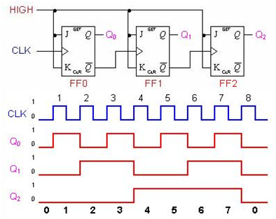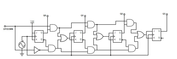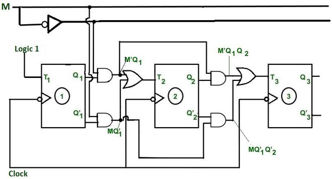

- #3 bit aynchornous ripple counter verilog code verification
- #3 bit aynchornous ripple counter verilog code code
Q <= 1’b0 / here 1'b0 means one bit number value zeroĮlse / if reset_in is low or false then q<= d_inįig. If (reset_in) / if reset_in is high or true then q <= 1'b0 * always block is the block who's statements are executed sequentially here the block will executed when clk_in is in positive edge or reset_in is in positive edge *// Output reg q / output variable of the d flip flop is (posedge clk_in or posedge reset_in) Input d_in, clk_in, reset_in / input variables of the d flip flop is defined
#3 bit aynchornous ripple counter verilog code code
Nand_g nand_4(qbar_out, q_out, x) / NAND agte module is calledĮndmodule Verilog Code for D flip flop with Asynchronous Reset module dflip_flop_asy_rst (q, d_in, clk_in, reset_in) Nand_g nand_3(q_out, qbar_out, y) / NAND gate module is called Nand_g nand_2(y, clk_in, dbar) /NAND gate module is called with y, clk_in and dbar parameter Nand_g nand_1(x, clk_in, d_in) /NAND gate module is called with x, clk_in and d_in parameter

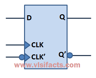
Not_g not_1(dbar, d_in) /NOT gate module is called with dbar and d_in parameter Output q_out, qbar_out / output of the D flip flop q_out and qbar_out where q_out and qbar_out is compliment to each other Input d_in, clk_in / input variable of D flip flop d_in is the data input and clk_in is the clock input * this module defines a d flip flop which will be design with NAND gate and NOT gate *// Module d_ff_st(q_out, qbar_out, d_in, clk_in ) Output e / e is the output variable of the NOT gate Input f / f is the input variable to the NOT gate Module not_g(e, f) / this block defines the NOT gate Output c / output variable of NAND gate is definedĪssign c = ~(a & b) / this assign is used to derive the value of c through a and bĮndmodule /module end with endmodule statement Input a, b / a and b is the input variable to the NAND gate Verilog Code for D flip flop using NAND gates module nand_g(c, a, b) //*each module contains statements that defines the circuit, this module defies a NAND gate which is named as nand_g*// Here, all the code is designed with D flip flop whether VHDL or Verilog code.
#3 bit aynchornous ripple counter verilog code verification
Verilog was originally for stimulation and verification of digital circuits, it is a hardware description language (HDL).


The output of the first flip-flop(JK FF1) is given as a clock pulse input for the second flip-flop(JK FF2). The toggling of JK FF1 continues for each clock pulse. For the next clock pulse, again JK FF1 will toggle its output to logic 0. During the first clock pulse, that is at the falling edge of the clock pulse, JK FF1 will toggle its output state to logic 1. Let us assume the initial state of flip-flop as Q BQ A = 00. The clock pulse is digitally counted at the output Q A and Q B, where Q A is the Least significant bit(LSB) and Q B is the most significant bit(MSB). The HIGH or logic 1 is maintained at the T-input of both flip-flops. The output(Q A) of the first flip-flop is fed as the clock input for the second flip-flop. The clock pulse input is given to the first flip-flop only.


 0 kommentar(er)
